July 27, 2018 / By meswpadmin
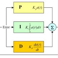
When discussing managing PID loops (Proportional, Integral, Derivative), there are three variables of control for performance optimization. There is an expression, “a little knowledge is dangerous”, this is definitely true when tuning PID loops. It is important to understand how PID loops operate to prevent damage to expensive equipment as well as improve performance. Knowing how each variable effects performance is vital to achieving the best performance possible in any application.
Proportional Gain
Proportional gain pushes the output based on how far you are from the set-point. The issue is that the closer you get to the set-point, the less it pushes. Eventually it doesn’t push any harder and the output can run continuously close to the set-point, but never get there. Proportional gain is added first with the other gains zeroed out.
PID Loops Integral Gain
Integral gain looks at the difference/error between the set-point and the output and then tries to even out that difference. This will cause the output to move above and below the set-point evenly. This action compensates for Proportional gain’s inability to get there. Integral gain is added in sparingly after Proportional gain is optimized as Integral gain amplifies the Proportional gain’s efforts and can easily cause a runaway condition.
Most applications work well with just Proportional and Integral gain, but let’s say you are controlling the temperature of an oven. If the oven temperature goes above the set-point, the product may be ruined or catch on fire. So, how do you get the oven to temperature without overshooting the set-point? This is where Derivative gain is needed.
PID Loops Derivative Gain
Derivative gain acts like a brake on the output. The more the controller tries to change the output, the more it counteracts the effort. Caution must be taken when adding Derivative gain as it opposes the efforts of Proportional and Integral gain and therefore should be added last. If Derivative gain is too high, then the output may not be able to act quickly enough, making the output unresponsive for the application.
System Responses
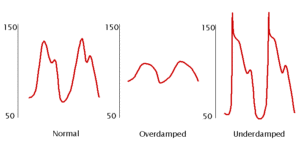
There are different desired outcomes that an application may call for, so knowing if you want a critically damped (normal), overdamped, or underdamped response in a system is necessary.

Critically Damped or Normal
The condition in which the damping of an system causes it to return as quickly as possible to its equilibrium position without oscillating back and forth about this position.
Overdamped
The condition in which damping of an system causes it to return to equilibrium without oscillating. The system moves more slowly toward equilibrium than in the critically damped system.
Underdamped
The condition in which damping of an system causes it to return to equilibrium with the amplitude gradually decreasing to zero. The system returns to equilibrium faster but overshoots and crosses the equilibrium position one or more times.
If you’d like more info on improving PID Loops performance, please give us a call at 317-844-7328 for more info or visit https://www.mesindy.com, we also have an online store at https://www.variablefrequencydrive.com. We have a staff of helpful electrical engineers ready to answer your questions today! If you have questions about when to use VFD cable read this post! When to Use VFD Motor Cables


