
Dynamometer Controls Manufacturer
A dynamometer or “dyno” for short, is a device for simultaneously measuring the torque and rotational speed (RPM) of an engine, motor or other rotating prime mover so that its instantaneous power may be calculated, and usually displayed by the dynamometer itself as kW or bhp.
In addition to being used to determine the torque or power characteristics of a machine under test, dynamometers are employed in a number of other roles. In standard emissions testing cycles such as those defined by the United States Environmental Protection Agency, dynamometers are used to provide simulated road loading of either the engine (using an engine dynamometer) or full powertrain (using a chassis dynamometer). Beyond simple power and torque measurements, dynamometers can be used as part of a testbed for a variety of engine development activities, such as the calibration of engine management controllers, detailed investigations into combustion behavior, and tribology.
In the medical terminology, hand-held dynamometers are used for routine screening of grip and hand strength, and the initial and ongoing evaluation of patients with hand trauma or dysfunction. They are also used to measure grip strength in patients where compromise of the cervical nerve roots or peripheral nerves is suspected.
In the rehabilitation, kinesiology, and ergonomics realms, force dynamometers are used for measuring the back, grip, arm, and/or leg strength of athletes, patients, and workers to evaluate physical status, performance, and task demands. Typically the force applied to a lever or through a cable is measured and then converted to a moment of force by multiplying by the perpendicular distance from the force to the axis of the level.
Principles of operation of torque power (absorbing) dynamometers
An absorbing dynamometer acts as a load that is driven by the prime mover that is under test (e.g. Pelton wheel). The dynamometer must be able to operate at any speed and load to any level of torque that the test requires.
Absorbing dynamometers are not to be confused with “inertia” dynamometers, which calculate power solely by measuring power required to accelerate a known mass drive roller and provide no variable load to the prime mover.
An absorption dynamometer is usually equipped with some means of measuring the operating torque and speed.
The power absorption unit (PAU) of a dynamometer absorbs the power developed by the prime mover. This power absorbed by the dynamometer is then converted into heat, which generally dissipates into the ambient air or transfers to cooling water that dissipates into the air. Regenerative dynamometers, in which the prime mover drives a DC motor as a generator to create load, make excess DC power and potentially – using a DC/AC inverter – can feed AC power back into the commercial electrical power grid.
Absorption dynamometers can be equipped with two types of control systems to provide different main test types.
Constant force
The dynamometer has a “braking” torque regulator – the power absorption unit is configured to provide a set braking force torque load, while the prime mover is configured to operate at whatever throttle opening, fuel delivery rate, or any other variable it is desired to test. The prime mover is then allowed to accelerate the engine through the desired speed or RPM range. Constant force test routines require the PAU to be set slightly torque deficient as referenced to prime mover output to allow some rate of acceleration. Power is calculated based on rotational speed x torque x constant. The constant varies depending on the units used.
Constant speed
If the dynamometer has a speed regulator (human or computer), the PAU provides a variable amount of braking force (torque) that is necessary to cause the prime mover to operate at the desired single test speed or RPM. The PAU braking load applied to the prime mover can be manually controlled or determined by a computer. Most systems employ eddy current, oil hydraulic, or DC motor produced loads because of their linear and quick load change abilities.
Power is calculated based on rotational speed x torque x constant, with the constant varying with the output unit desired and the input units used.
A motoring dynamometer acts as a motor that drives the equipment under test. It must be able to drive the equipment at any speed and develop any level of torque that the test requires. In common usage, AC or DC motors are used to drive the equipment or “load” device.
Detailed dynamometer description

Electrical dynamometer setup showing engine, torque measurement arrangement and tachometer
A dynamometer consists of an absorption (or absorber/driver) unit, and usually includes a means for measuring torque and rotational speed. An absorption unit consists of some type of rotor in a housing. The rotor is coupled to the engine or other equipment under test and is free to rotate at whatever speed is required for the test. Some means is provided to develop a braking torque between the rotor and housing of the dynamometer. The means for developing torque can be frictional, hydraulic, electromagnetic, or otherwise, according to the type of absorption/driver unit.
One means for measuring torque is to mount the dynamometer housing so that it is free to turn except as restrained by a torque arm. The housing can be made free to rotate by using trunnions connected to each end of the housing to support it in pedestal-mounted trunnion bearings. The torque arm is connected to the dyno housing and a weighing scale is positioned so that it measures the force exerted by the dyno housing in attempting to rotate. The torque is the force indicated by the scales multiplied by the length of the torque arm measured from the center of the dynamometer. A load cell transducer can be substituted for the scales in order to provide an electrical signal that is proportional to torque.
Another means to measure torque is to connect the engine to the dynamo through a torque sensing coupling or torque transducer. A torque transducer provides an electrical signal that is proportional to the torque.
With electrical absorption units, it is possible to determine torque by measuring the current drawn (or generated) by the absorber/driver. This is generally a less accurate method and not much practiced in modern times, but it may be adequate for some purposes.
When torque and speed signals are available, test data can be transmitted to a data acquisition system rather than being recorded manually. Speed and torque signals can also be recorded by a chart recorder or plotter.
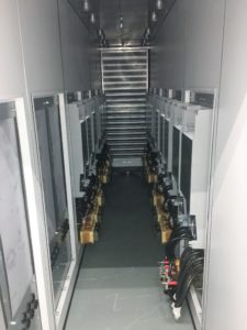
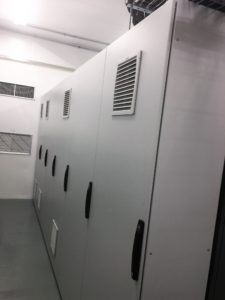
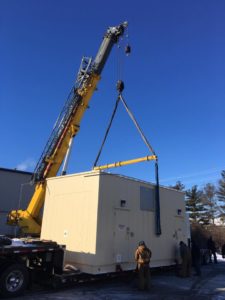
We use Nidec Control Techniques modular drives to design our systems. Our systems have been in service since 1995 and we have had very few failures. We put together a 4500HP helicopter test stand, see pictures below.
Dynamometer Controls Built for High Performance Test Stands
What allows MES Indianapolis to build the best Dynamometer Controls Systems:
- Our dynamometer controls have distinct advantages in design and implementation
- The ability to switch between speed, torque or torque regulated speed follower modes
- Highest switching frequencies such as 4kHz, 8kHz, 12kHz, and 16kHz for the most efficient operation of motors.
- While our competition typically runs at 2 kHz to limit the amount of heat losses in the inverter.
- The Standard inverter controls motors up to 550Hz
- Also, the High Speed inverter controls motors up to 1600Hz with MES supplied high speed components.
- Horsepower ratings from 100HP – 5000HP for a single motor.
- Universal feedback options built-in as standard a standard option into the inverter allowing for any feedback device.
- The dynamometer control inverter has an onboard PLC for logic programs
- Also, the PLC has an industry standard IEC61131-3 programming environment for efficient system design and configuration
- As well as, MCi modules can be added to execute larger programs for advanced system control capability
- Integrated dual port Ethernet switch provides simple connectivity using standard connections
- Onboard real-time Ethernet (IEEE 1588 V2) uses RTMoE (Real Time Motion over Ethernet) to provide fast communication
- Three system expansion ports are available to fit additional fieldbus, position feedback and I/O options
- Safe torque off as standard meeting safety needs with optional safety modules to meet the highest standards needed in the industry
- Regenerative systems available on all applications reducing power quality issues and saving money on power demand charges
Testimonials
Look what our customer, Mustang Advanced Engineering has to say about our Dynamometer Control Systems: https://mesindy.com/testimonials/
So, when you’re looking for the best in dynamometer control systems, give us a call. MES built the controls on a test stand at Tesla Motors. https://www.tesla.com/.
In conclusion, MES has built many controls for dynamometer test stands which are out in advanced test environments all over the country. Call us today for a quote!